This article was first published on Automation Service.
When you’re looking for a transmitter to mount on one of your tanks, you need to determine the right-fit calibration range for the application. While an engineer can certainly assist you in selecting the correct calibration range, you can get a very close idea of what you’ll need using just a few pieces of key information about your processes.
What you need to know about your process to determine calibration range
Step 1: Determine your fill fluid specific gravity (sf) and process fluid specific gravity (sp)
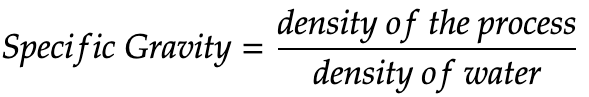
Specific gravity is the ratio of
- the density of a substance to
- the density of water at a specified temperature
Step 2: Determine maximum process fluid height (H) in your preferred units
Step 3: Determine the distance between the high side process connection (bottom tap) and transmitter (h) in your preferred units
Calculating calibration range values
Given the values you’ve determined above, you’ll need to calculate zero suppression or elevation, span, and finally, your calibration range. Direct connection seals do not require zero suppression or elevation, but will still require calculation of span and calibration range.
Step 1: Calculate zero suppression or zero elevation
Let’s start with zero suppression. You’ll need this value to calculate your calibration range if your transmitter is mounted below your process connection. To calculate zero suppression, multiply the distance between the high side process connection and transmitter (h) by your fill fluid specific gravity (sf).
![]()
If your transmitter is mounted above your process connection, you need to calculate zero elevation. You’ll notice the equation is similar to zero suppression, but the value for the distance between the process connection and transmitter (h) will be negative. So, to calculate zero elevation, multiply the negative value for the distance between the high side process connection and transmitter (h) by your fill fluid specific gravity (sf).
![]()
*Note: a negative value for (h) indicates the direction of head effect in a capillary system and that there’s zero elevation
Step 2: Calculate span
Next, calculate span. Span is your maximum process fluid height (H) multiplied by your process fluid specific gravity (sp).
![]()
Step 3: Calculate your calibration range
After completing the first two steps, you can finally calculate your calibration range.
If you calculated zero suppression in step one, your calibration range would be from your zero suppression value to your zero suppression value added to span.
![]()
If you calculated zero elevation in step one, your calibration range would be from your zero elevation value to your zero elevation value added to span.
![]()
Examples – shown in inches
Example 1 – Single Direct Connection With No Suppression or Elevation
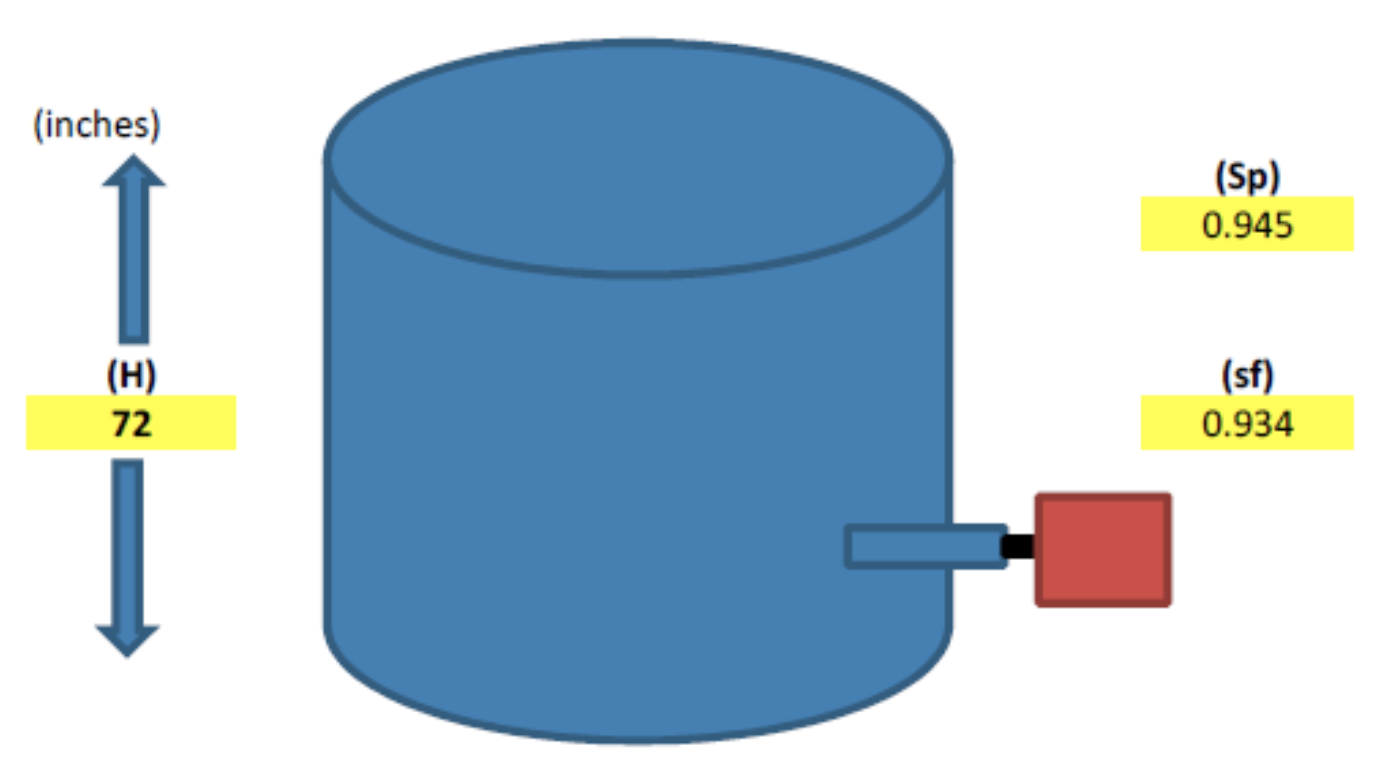
| Given values | Calculated values | ||||
| (H) maximum process fluid height (inches) | 72 | Span (inches) | 68.04 | ||
| (Sp) process fluid specific gravity (lb/ft3) | 0.945 | Calibration range values (inches) | 0 | to | 68.04 |
| (h) distance between process connection and transmitter(inches) | No suppression or elevation | ||||
| (sf) fill fluid specific gravity (lb/ft3) | .934 |
Example 2 – Single Capillary With Zero Suppression
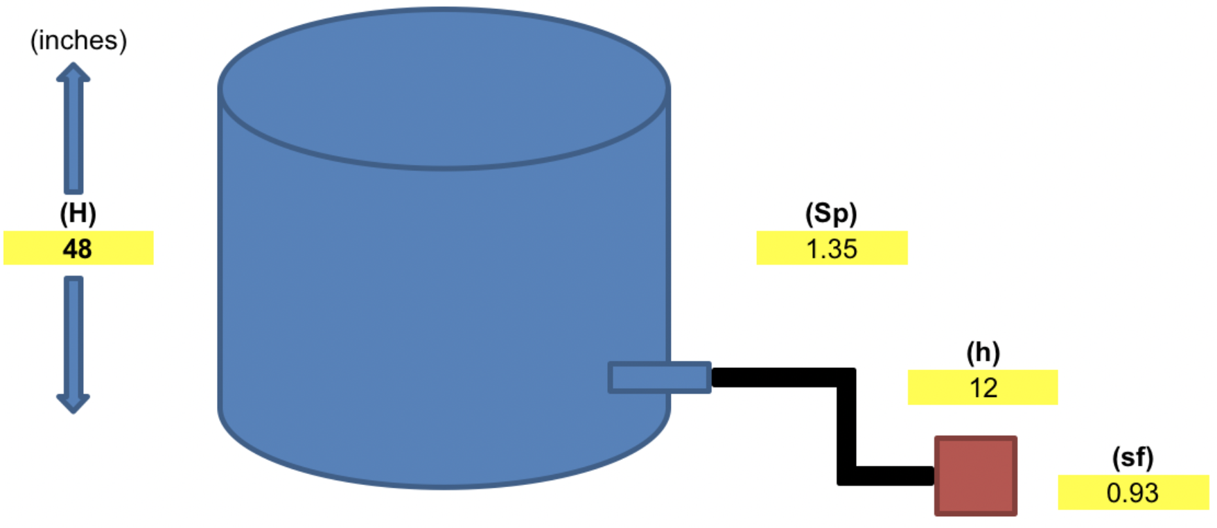
| Given values | Calculated values | ||||
| (H) maximum process fluid height (inches) | 48 | Span (inches) | 64.8 | ||
| (Sp) process fluid specific gravity (lb/ft3) | 1.35 | Calibration range values (inches) | 11.16 | to | 75.96 |
| (h) distance between process connection and transmitter(inches) | 12 | Zero suppression | 11.16 | ||
| (sf) fill fluid specific gravity (lb/ft3) | 0.93 |
Example 3 – Single Capillary With Zero Elevation
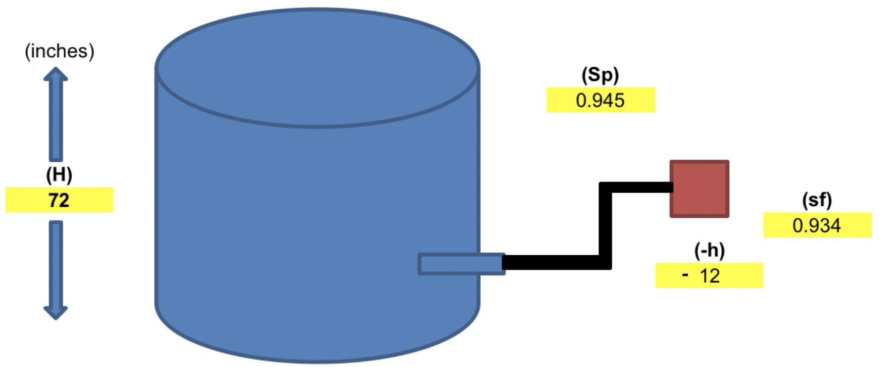
| Given values | Calculated values | ||||
| (H) maximum process fluid height (inches) | 72 | Span (inches) | 68.04 | ||
| (Sp) process fluid specific gravity (lb/ft3) | 0.945 | Calibration range values (inches) | -11.2 | to | 56.84 |
| (-h) distance between process connection and transmitter (inches) | -12 | Zero elevation | -11.208 | ||
| (sf) fill fluid specific gravity (lb/ft3) | 0.934 |
Example 4 – Two Capillary with Zero Elevation
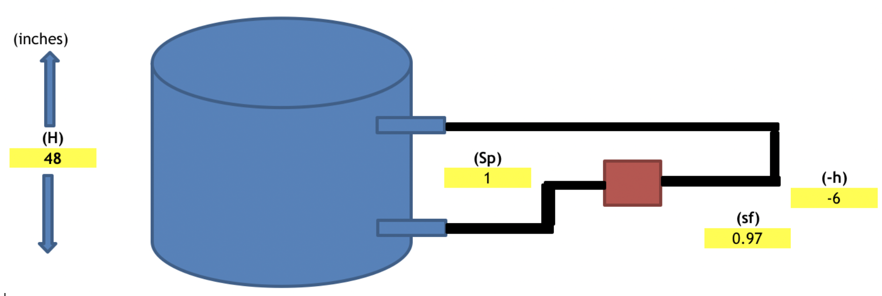
| Given values | Calculated values | ||||
| (H) – maximum process fluid height (inches) | 48 | Span (inches) | 48 | ||
| (Sp) process fluid specific gravity (lb/ft3) | 1 | Calibration range values (inches) | -5.82 | to | 42.18 |
| (-h) – distance between process connection and transmitter(inches) | -6 | Zero elevation | -5.82 | ||
| (sf) – fill fluid specific gravity (lb/ft3) | 0.97 |
Example 5 – Two Capillary With Zero Suppression
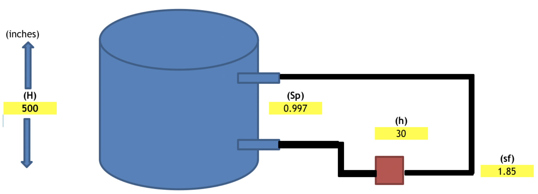
| Given values | Calculated values | ||||
| (H) – maximum process fluid height (inches) | 500 | Span (inches) | 498.5 | ||
| (Sp) process fluid specific gravity (lb/ft3) | 0.997 | Calibration range values (inches) | 55.5 | to | 554 |
| (h) – distance between process connection and transmitter(inches) | 30 | Zero suppression | 55.5 | ||
| (sf) – fill fluid specific gravity (lb/ft3) | 1.85 |